Click here for MegaSquirt® MegaManual™ Information, Guides, and Links
A major addition to the MicroSquirt® code is MAF (mass air flow) sensor capability and also a combined MAF/ MAP mode. Rather than calculating the air flow from the VE table and manifold pressure (MAP), the mass air flow sensor measure the amount of air directly. In some cases this can make the engine easier to tune, and better at adapting to changing engine parameters. On the other hand, the MAF sensor itself can present an significant airflow restriction to the engine (limiting power), and sometimes can have range limitations if the engine flow a lot more (or less) than the application it was designed for. This change and all others following apply to both MicroSquirt® and MegaSquirt-II™.
Note that you should not use the automatic mixture correction option with MAF-Only, it will not work.
When the MAF option is selected with a v1 MicroSquirt® EFI controller, the sensor would normally be wired to the MAP pin. If, however, the combined MAF/ MAP option is selected, then MAF MUST be connected to the Barometric/second EGO sensor pin (#29) (you cannot use the knock pin with a v1 MicroSquirt® EFI controller, it is not brought out to the AMPseal connector on MicroSquirt®).
However the v2 MicroSquirt® EFI controller board has AD7 on pin 5 of the Ampseal so you can use it for MAF. Plus, if you have Frequency output MAF, you MUST use this pin because it is simultaneously tied to processor pin T7 which is the only timer pin that has a special read Frequency period mode, so it automates this process, making it much more accurate.
The MAF/ MAP blend option is used to cover the entire rpm/ load range with a high degree of resolution. Depending on the engine design, it may be that one or the other sensor is unsuitable for either the low end or the high end. By combining them, the entire range can be effectively covered. Perhaps more important, dual sensors are needed for observer/ model based tuning systems, where the two sensors plus a mathematical model of flow through the throttle plate are all used to provide a best prediction of engine performance. The prediction is self-correcting based on the sensor values. This use of two independent load sensors is common in most late model factory cars.
It is implemented by using:
If desired, the MAF/MAP blend operation can be reversed to use MAF at low rpm and MAP at high rpm. The logic is similar to the Alpha_N mode - in fact you can use a blend of all 3, although this option remains untested.
The Mass Air Flow (MAF) mode implemented in MS-II™, MicroSquirt® and Sequencer™ controllers uses the mass air flow rate signal obtained from an external MAF sensor to determine cylinder mass air, and determines a corresponding mass of fuel based on target lambda and the stoichiometric air/fuel (A/F) ratio of the fuel used:
Where:
For MAF mode, the calculation of engine load (used for spark advance table indexing) follows the specification of SAE OBDII PID$43, also known as LOAD ABS, which is the normalized value of air mass per intake stroke displayed as a percent:
| LOAD_ABS = | 100*[air mass (g)/intake stroke] |
|
Where STP = Standard Temperature and Pressure = 25 °C, 29.92 in Hg (101.3 kPa) BARO, WOT = wide open throttle.
The characteristics of LOAD_ABS are the following:
If you select one of the MAF options, you must input a MAF sensor calibration curve (or use the default Ford curve). This is similar to the coolant sensor curve, in that both are non-linear and can not be handled as a simple scale and offset. The best way to obtain such a curve is by measuring the air flow through a flow bench. In doing this it is vital that the entire air duct be included in the measurement. If this is not feasible, then a shorter correction table is provided as a tuning input. This table consists of MAFFlow vs % correction arrays, where as usual 100% means no correction. The final MAF is calculated by:
There is more information on tuning the MAF curve below.
Ford MAF Sensor Response Curve
This is a typical response curve for a Ford Mustang V8 (with sequential fuel injection) MAF sensor:
| Volts | Air Flow (mg/sec) |
|---|---|
| 0.50 | 3250 |
| 1.00 | 7910 |
| 1.50 | 15580 |
| 2.00 | 27990 |
| 2.50 | 46730 |
| 3.00 | 72570 |
| 3.50 | 107140 |
| 4.00 | 148340 |
| 4.50 | 198450 |
| 5.00 | 276730 |
Ford MAF Sensor Pin-Outs:
This Ford Mustang MAF sensor has 4 pins, with A, B, C, and D imprinted on the sensor case:
| Pin | Function | MicroSquirt® Connection |
| A | Switched 12 volts | Main Relay pin 87 [RD] |
| B | Ground | Ground to same spot as MicroSquirt® [BLK] |
| C | MAF signal ground | Connect to Pin 20 [WHT/BLK] |
| D | MAF output signal | |
| E & F | not used | not used (if exist) |
The rectangular connector MAF sensor has 5 pins denoted by A, C, D, and E, with the B pin missing:
| Pin | Function | |
| A | Switched 12 volts | Main Relay pin 87 [RD] |
| C | Ground | Ground to same spot as MicroSquirt® [BLK] |
| D | MAF signal ground | Connect to Pin 20 [WHT/BLK] |
| E | MAF output signal |
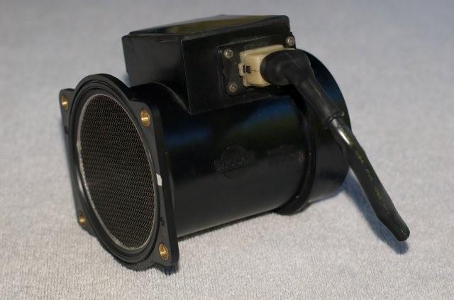
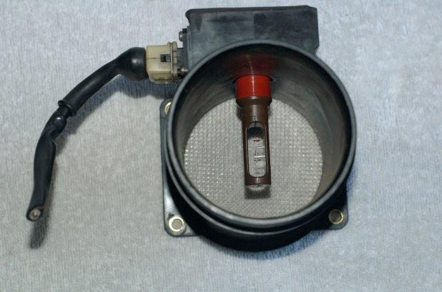
An alternative to the Ford MAF sensor is the Infiniti (Nissan) Q45 MAF sensor, which apparently flows more air than any other stock MAF sensor. It has an clear inside diameter of 3.19 inches (80mm). These are cheap on eBay. Like the Ford MAF sensor, it is voltage-out (not frequency), so it is relatively easy to hook-up to MegaSquirt-II™.
In OEM wiring harnesses, the wires are usually:
The mass air flow to voltage out signal is typically like this:
| Volts | Air Flow (mg/sec) |
|---|---|
| 0.50 | 1480 |
| 1.00 | 6560 |
| 1.50 | 17510 |
| 2.00 | 36260 |
| 2.50 | 66260 |
| 3.00 | 125660 |
| 3.50 | 188550 |
| 4.00 | 291120 |
| 4.50 | 427450 |
| 5.00 | 605990 |
There is a full output curve for this (and other) Nissan MAF sensors in this spreadsheet.
Unfortunately it is nearly impossible to have a perfectly suitable 'default' MAF transfer map because of the sensitivity of installation to external factors.
For example, there are a bunch of different curves out there for the same 70mm MAF. We have the means to measure MAF sensors directly and compare it with an accurate laminar flow element to determine mass air flow. The problem is that when the MAF sensor is bolted to the vehicle none of the curves match (likely due to the inlet plumbing affecting the airflow).
The MAF ducting is important to its air flow/output voltage curve, yet very few aftermarket manufacturers know this. If you change any of the ducting, remove/add an air cleaner, or even put your hand in front of the airstream you will see a calibration change. You can see this just by running the engine at idle and remove the air cleaner or stick your hand in front of the airstream while watching the O2 readings. Idle (i.e. low mass air flow rates) region is most sensitive. In the end the curve measured on the bench is the most accurate but it still needs tweaking when installed in the vehicle.
To tune, you need to know that a certain voltage output from the MAF means a specific grams of air per sec going through the MAF. You can get that from documentation or OEM curve provided the sensor location and ducting is exactly as it was stock from the factory or by having the MAF + ducting flowed or by using an accurate O2 sensor. So if you have a non-OEM setup you need to tweak the transfer function on the car.
In the case of having a non-OEM set-up, you start with some curve that will at least allow the car to run, then tuning the calibration curve to make the O2 reading match the target O2 reading. Do this for a few rpms and you can fit it all to King's equation which captures the shape of the MAF curve with only 2 or 3 parameters.
This is relatively easy with a narrow band exhaust gas oxygen sensor (or a wideband EGO sensor, just try to tune near the stoich point to minimize errors). You can get a good feel for the accuracy of a MAF curve by using a cheap NB sensor. The NB is accurate because it limits itself to one point, and all you really need, for most purposes, is that 1 AFR point at a few different flows (rpms).
Put the car in part/neutral and run the engine while monitoring the O2. Adjust the transfer function to get a stoichiometric mixture (i.e. 0.45 volts with a narrow band EGO sensor, or 14.5:1 AFR with a wideband EGO sensor/controller), then rev the engine up a bit and adjust the next bin. You will see a trend where it is good at low rpms but needs tweaking on the high end (or reverse). You can move the bins around to capture the place where it needs to be tweaked.
The MicroSquirt® code can be used on MegaSquirt-II™, and thus MS-II™ can use a MAF. The set-up is described above. You have to connect the 0 to 5V MAF output signal (pin D on a Ford MAF sensor) to an appropriate input port (through a 1K Ohm resistor). This can be:
| Original Function | 40-Pin Socket Pin | Port | Jumper to | Notes |
| MAP | 23 | AD0 | MAP sensor pin 1 | MAF Only |
| Baro | 29 | AD6 | MAF/MAP Blend | |
| Knock | 30 | AD7 | MAF/MAP Blend |
Note: on a V3 main board, you can use one of the SPR jumpers to bring the MAF signal in through the DB37 connector. With the relay board, it gets more 'custom'.
In any case, you should run the MAF ground to one of the sensor 'Ret' positions.
You will also need to connect the MAF to switched 12 Volts (if it is not a Ford sensor, check if your sensor requires some other voltage) and ground, as appropriate.
To assist in the calibration and use of Mass Air Flow sensors, an analysis program has been developed to aid in the characterization of MAF transfer curves. This Windows program is called the MAF Analyzer and is available for download here:
To use the program, simply unzip in an empty directory and double-click on the application to execute - please read the user's manual for the MAF Analyzer included in the archive above. Below are some links for pre-run files that can be uploaded to MS-II™/MicroSquirt®/Sequencer™ controllers:
These files go in the project folder's \inc\ sub-directory. This directory might already exist, or you may have to create the directory. You must rename the file you want to load to 'maffactor.inc'. Then , in TunerStudioMS, go to 'Tools/Calibrate MAF Table' and click the 'Write to Controller' button. TunerStudio will show the progress as the table is written to the controller.
You can have more than one MAF .inc file in your \inc\ sub-folder (more recent versions of TunerStudioMS have these built in as defaults with the files already in place - if they aren't in place, just copy the following files to the project folder's \inc\ sub-folder).
You can select between them in TunerStudioMS (that is why there is the 'Select Settings' test in the TS MAF burning dialog - a drop down selection box will appear if more than one file has been defined). To define more files this, you must edit the INI file where it says,
[ReferenceTables]

    tableWriteCommand 	= "t" ;

    referenceTable = mafTableBurner, "Calibrate MAF Table..."
    	;topicHelp = "http://www.megamanual.com/mt28.htm#??"
        tableIdentifier = 003, "MAF Table"
        adcCount 	= 1024 	; length of the table
        bytesPerAdc 	= 2 	; using words
        scale		= 1 ; scale before sending to controller
    	solutionsLabel	= "MAF Sensor"
    	solution	= "MAF Sensor", 	{ table(adcValue, "maffactor.inc") }
and add lines that define new file names that have been placed in the project's \ini\ folder, like:
    	solution	= "Ford Lightning MAF", 	{ table(adcValue, "maffactor_1L3F_Lightning.inc") }
		solution	= "Infiniti Q45 MAF", 		{ table(adcValue, "maffactor_Q45.inc") }
		solution	= "GM LT1/LS1/LS2 MAF", 	{ table(adcValue, "maffactor_lsx.inc") }
    	etc.